9610-40 Photovoltaic Earthing Resistance Tester
1, in accordance with "IEC61730-2 MST13" photovoltaic industry grounding continuity test; with 2.5 times the component protection current test, 120s, resistance is less than 0.1 ohms. 2. General requirements for the safety performance testing principles of " GB4706 " and " IEC60335 " for household and similar electrical appliances 3, in line with " GB7000 " " IEC60598 " lamps general safety requirements and tests 4 , in line with " GB4943 " " IEC60950 " information technology equipment safety 5 ã€Measurement method of contact current and protective conductor current in accordance with GB12113 and IEC60990 6 , no contact current, 50/60Hz dual-frequency output, to meet the test requirements of domestic and export products 7 , no pressure regulator constant current output, low noise, low failure rate 8. LPA (Linear) Technology Leading Domestic, Pure Waveform of Output, Green and Environmental Protection, Complying with IEC , UL and Other Electrical Safety Regulations 9 , optional display with measured resistance voltage value instead of resistance value 10 , optional RS-232 , RS-485 , remote control and other interfaces to achieve test network Technical indicators: Pick up No-load output voltage <8VAC Output current range and accuracy 5-40A ± (2% setting ) ; customizable 60A Output current stability Less than 0.3% ( 10A/100mΩ ) Output frequency range and accuracy 50Hz/60Hz ±0.2%, users choose Earth resistance test range and accuracy 5-600mΩ (5-10A) ; 2 – 200mΩ (11-25A) ; 2 – 150 mΩ (26-30A) ; 2—120mΩ ( 31—40A ); ± (2% Setpoint + 3mΩ) Test time range and resolution 0 , 1-999s , resolution 1s , 0s is continuous output one PLC remote control Signal input : start , stop , UI Blue Screen LCD Communication Interface RS232 (optional) Correction method Can be entered through the front panel parameters, software-based correction working environment 0-40 °C , 20-80%RH Input voltage 220Vac±10% Input frequency 50/60Hz ± 5% fuse Fuse 8A/250V Dimensions 280mm(W)×89mm(H)×430mm(D) Product attachments: Power Line (8A) × 1 Grounding resistance test clip × 2
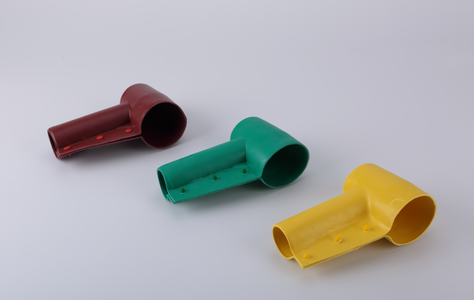
Bushing Cover For Transformer, in other words, A transformer insulation protective sleeve belongs to the field of power equipment. Its main body is a set body. The sleeve body is a hollow rectangular structure. One end of the sleeve body is connected with an outlet, and the top of the other end is provided with a cylindrical wiring port, wiring port, and sleeve The outlet is provided with an opening edge, and the opening edge is provided with a buckle, characterized in that: the outlet is provided with an annular clamp ring, the top of the clamp ring is extended with a convex edge, and the convex edge is provided with a buckle on the edge Corresponding to the card hole, the sleeve body is made of synthetic silicone rubber. The utility model has simple structure and reasonable design, the synthetic silicone rubber material will never be deformed, and the flexibility and tearability are high; the installation is convenient, and the buckle structure is convenient for maintenance. Disassembly and re-use; the setting of the clamp ring can effectively stabilize the cable and prevent friction and loosening.
Transformer Bushing Covers,Cover Bushing,Busbar Insulation Cover,Transformer Bushing Cover ShenZhen FUJI Electric Material Co., Ltd , https://www.sinofuji.com
Land
Electricity
Resistance
General
regulation
grid 