Introduction of lithium battery charger composed of domestic new IC
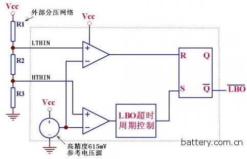
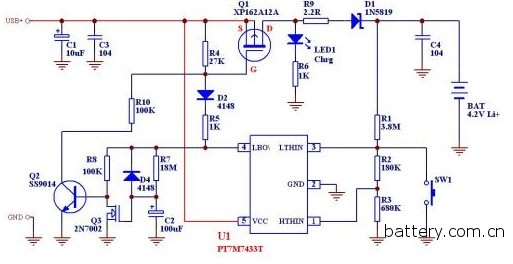
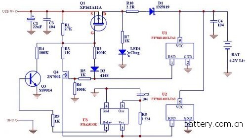
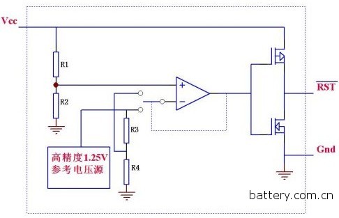
In view of this, the author introduces two lithium battery chargers composed of domestically produced new ICs, which provide far more performance than the LM324 solution at roughly equivalent overall cost, with high novelty and market prospects. PT7M7433T is one of the most highly accurate series of voltage detectors designed by Shanghai Bailitong Co., Ltd. Its detection accuracy is less than 1mV in the range of 0-Vcc (5.5V), and the deviation of the detection value of the batch IC is <±2.5. %, which fully guarantees the performance consistency and high overall performance of the batch products, we can use it with a small number of external circuits to form a relatively simple lithium battery charging circuit. The internal block diagram and brief introduction of the IC are as follows: (Figure 1) The IC contains a high-precision 615mV reference voltage source, two comparators, an RS flip-flop and some other logic circuits. Its general function is: VCC voltage or other voltage to be detected is connected through a voltage divider network composed of R1-R3. The LTHIN /HTHIN detection pin of the IC, when the voltage to be tested drops causing the LTHIN pin to be lower than 615mV, the output pin LBO outputs a low level, and if the voltage to be measured rises, the HTHIN pin is higher than 615 mV, after internal logic After the judgment and simple delay, the output pin LBO outputs a high level. The charger circuit installed with this IC is as follows (Figure 2) The workflow is roughly as follows: When connected to the Li+ battery and the power supply, the IC detects the battery voltage through the network composed of R1/R2/R3. If the battery voltage is lower than 3.3V (determined by the resistance value of R1-R3), or press Press SW1, and the voltage of IC3 pin is lower than 615mV, then IC4 pin outputs low level, pulls the gate of Q1 low through R5/D2, and turns on the battery through Q1/R9/D1 Charging, when the battery voltage rises all the way up to 4.20V, at this time, the IC's 1 pin voltage is higher than 615mV, the IC internally judges and delays, so that the 4 pin outputs a high level, thus turning off the large current charging channel, but 4 feet The high level simultaneously supplies power to the R7/C2 charging loop, causing the gate voltage to Q3 to rise slowly, and providing a path to R8 to cause Q2 to conduct, and R10 provides a weaker on-current to Q1. It is slightly turned on to provide a less supplemental charging current to the battery. According to the component parameters shown in the figure, after about ten minutes, due to the continuous charging of C2, the terminal voltage, that is, the gate voltage of Q3, rises until Q3 is turned on, thereby turning off Q2, so that the entire charging process ends. There are still some shortcomings in the above scheme. For example, the detection accuracy is determined by the accuracy of the external resistor R1/R2/R3. For the overdischarged battery (the battery terminal voltage is lower than 2.8V), there is no small current precharge process. The 10-minute replenishment charging time of the solution is not enough for a larger capacity battery. Therefore, in view of the above deficiencies, we also provide a solution with a slightly higher cost and better performance: (Figure 3) At first glance, this solution uses three ICs, but U1 and U2 are SOT-23 or TO-92 packages, just like ordinary triodes, the price is 2-3 triodes, and U3 ( PT8A2513NE) is also used in the TO-94 package. The shape is similar to that of the triode, and the price is quite cheap. However, this circuit can intelligently judge whether the battery is over-discharged, decide whether to use a small current pre-charge when starting charging, and U3. After that, the supplementary charging process in the later stage of charging is extended to about one hour! Let us first introduce the functions of several ICs in this circuit: (Figure 4) is the internal block diagram of U1/U2. These two ICs only have different values ​​of internal resistors R1/R2. Their functions are also very simple: when Vcc is lower than the IC setting value (depending on the IC number, The internal R3/R4 resistance values ​​are also different, resulting in different detection voltage values. For PT7M6128, it is 2.80V), the RST pin outputs a low level, and when Vcc is higher than 1.05 times the nominal value (for example, for PT7M6140, this value) The 1.05x4.0 = 4.20V) RST pin outputs a high level. The other IC of the above circuit (PT8A25 13) is a very simple but extremely stable delay IC whose delay time depends only on the frequency of the OSC pin. In fact, the IC is used to control the output by dividing the OSC oscillation frequency by 32768 times. The reason why this circuit is used instead of a general-purpose IC such as the LM555 or CD4060 is because it is relatively more accurate in timing (other ICs are not divided) and has a longer timing (up to several hours). And the circuit is simpler, in a TO-94 or SOT-23-4 package, just like a triode. The price is similar to that of the CD4060, and the effect is much better. At this point, everyone must have a general understanding of the workflow of Figure 3: connect the battery and charger, if the battery voltage is lower than 2.8V, the U1 output is low (the U2 output is also low), so the loops of R3 and R4 are not connected. Only the R2 loop is turned on, providing a weak turn-on to Q1, which outputs about a few milliamps of current to pre-charge the battery. When the battery voltage rises above 2.94V (1.05X2.8) or just after the battery voltage is connected When it exceeds 2.94V, U1 outputs a high level and U2 continues to output a low level (the battery voltage has not reached 4.2VJ). At this time, the R2 path is turned off and the R3 path is turned on (because Q4 is turned on and its source level is Low - because U1 output is pulled low), so that Q1 is fully turned on by a smaller value of R3, providing a high current constant current charge of hundreds of milliamps, and when this constant current charging process is slowly charged When the Li+ battery terminal voltage rises to 4.2V, U2 also outputs a high level to turn off Q4, but it also supplies power to U3 to cause U3 to start working, so U3 triggers Q3 to turn on R4 to provide a small supplementary charging current. Until U3 reaches the timing time and then closes Q3, then the whole The charging process is completely over. In contrast, the second solution increases the pre-intelligent determination of battery status and automatic pre-charging process, as well as extending the time of the end of the supplementary charging process, the charging current is adjustable at each stage and the supplementary charging time is adjustable (a few minutes to several hours), so the program for lithium battery, has better accuracy and safety, coupled with inexpensive, function more perfect, I believe that the market will soon replace affordable charger especially those cheap mobile phone battery charging Device. Car Wash Machinery,Touchless Car Wash Machine,Car Washing Machine Systems,Car Wash Machine With Five Brushes Wuxi Golden Boat Car Washing Equipment Co.,Ltd , https://www.carwashauto.com