Surge test technology normal operation implementation method
Runde produce end feed Brass Fittings for European market.the quality satisfy Kitemark,end feed brass fittings,EF brass fittings,solder joint brass fittings,EN1254 brass fittings,brass pressure fittings,wrot joint brass fittings. end feed brass fittings,EF brass fittings,solder joint brass fittings,EN1254 brass fittings,brass pressure fittings,wrot joint brass fittings Taizhou Runde Company , https://www.zjbronzefittings.com
Energy measurement test The medical electrical equipment international standard IEC60601-1 contains a number of surge tests to ensure that the device under test operates normally under the conditions of defibrillation pulses. These tests are described in Figures 9, 10 and 11 of IEC 60601-1. Each test requires a 5000V power supply capable of supplying 400 J. The power output on the tester is approximately 360 J (worst case). The three figures in the standard describe different ways of transmitting this pulse to the device under test.
The two methods described in IEC 60601-1:2005 Figures 9 and 10 are the normal mode and differential mode tests, respectively, and can be used to check the separation between the signal input/output components and the patient connection components. A voltage divider network is used to monitor the voltage change of the signal input/output components when the 360-J pulse is applied.
The IEC60601-1 safety standard General Requirements 2005 adds a new energy measurement test that was introduced into this general medical standard from the safety requirements of the IEC60601-2-49 multifunction patient monitoring device. This new requirement states that the instrument connected to the patient can reduce the defibrillation energy delivered by a 100Ω load by up to 10%.
All three of the above tests and other surge tests in the AAMI and IEC medical standards use the 5000-V/400-J engine, except that the waveform components and application technology are different. Because of this similarity, test equipment manufacturers have been able to develop a tester that meets multiple standards at the same time. By looking at the IEC60601 defibrillation tester's documentation, the user can know exactly which standard tests the device can perform; in addition, the connection information for each test method can be viewed. 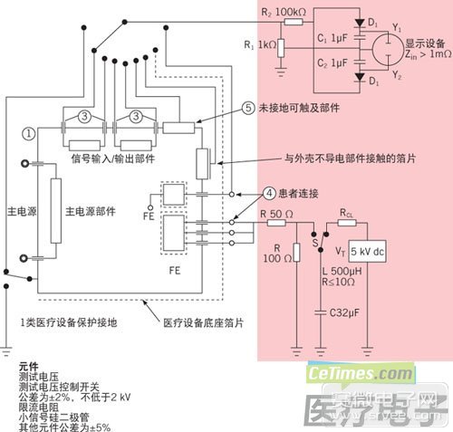
Figure 1: IEC60601-1:2005 Figure 9 - Defibrillation application components, the test voltage is applied to the patient connection as shown in the example in Figure 1 (IEC60601-1:2005 Figure 9), by determining circuit component values ​​and tolerances The pulse from the 5000-V/400-J power supply can be controlled in the same way as the IEC/AAMI standard. The area shaded in red in the figure shows the circuitry that the defibrillation surge tester should provide. The circuit in the lower part of the red box area is the universal 5000-V/400-J surge power supply. Below the circuit is a list of components and tolerances; note that all tolerances for surge power supplies are ±5%. Waveform elements vary from standard to standard, but component tolerances for surge power supplies are also ±5%.
Calibration ensures that component tolerance values ​​meet the requirements. For a defibrillation surge tester that has not been used or calibrated, the user can be confident that its tolerance is within the above numerical range. However, unless the surge tester is turned on to recheck the component values ​​(which would invalidate the calibration), it is not possible to directly confirm whether the instrument is operating properly during the calibration cycle. Below, we will introduce some ways to check the calibration status without opening the surge tester.
The waveform comparison method IEC60601-1:2005 uses defibrillation surge testers for all three tests (Figures 9, 10, and 11). The pass/fail point is established on the pulse from the 5000-V/400-J power supply. The device under test is based on the transmission. However, if there is no reference data (except for inaccessible component values ​​and tolerances), the power output cannot be confirmed solely based on the information provided in IEC 60601-1:2005. In addition, because the surge tester conforms to IEC 60601-1:2005 requirements only depends on component tolerances, only component tolerances can be verified even if the calibration passes the ISO17025 standard. 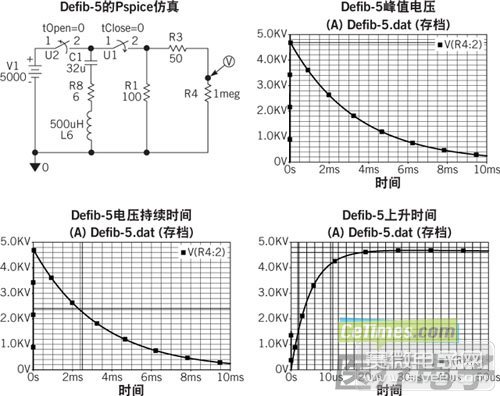
Figure 2: IEC60601 display current and its defibrillation waveforms
Waveform Comparison Test Method This method compares the new waveform generated by the defibrillation surge tester to the waveform in the initial calibration data packet when the instrument is receiving. If there is no such information, the general analog waveform provided in FIG. 2 can be used. This is a simple and quick way to verify the output of a surge tester. Figure 3 shows an example of an initial reference waveform for reference in the test.
The last point: The 5% component tolerances specified by the IEC 60601-1:2005 standard seem to be very strict, but our experience is that some output variations may occur even if all tolerance standards are met. If your defibrillation surge tester output data is not ideal, you can't immediately make a conclusion about the current calibration status of the instrument. Further tests are required. When using a standard defibrillation tester, the output peak voltage will be between 4500V and nearly 5000V due to the different tolerances and qualities of the components used.
1. Use a high voltage high frequency oscilloscope probe. We have achieved very good results using the Tektronix P6015 (available in the secondary market at a reasonable price).
2. Use a digital oscilloscope. The input signal is set to 1.00 kV/vertical division and 500.0 μSec/horizontal division.
3. If your defibrillation surge tester has multiple waveform networks, make sure it is set to 50 ohms, 500 μH.
4. Set the front panel meter to 5000V, indicating that the internal power supply is charged to 5000V (the output will be below this value; see Figure 2 in this article).
5. Start the defibrillation surge tester so that the current is transmitted to the open circuit output and only the high voltage probe is connected.
6. Observe the scope display. The output peak should be between 4500 and 4900V (not 5kV).
7. Find the midpoint of the voltage peak waveform on the waveform duration side. The waveform should conform to the initial waveform and position near 2.42 milliseconds.
8. If the waveform peak or its duration is slightly lower than expected, the defibrillation surge tester may not be able to transmit the required 360J of energy. Further tests should be carried out (see section on evaluation of the accuracy of energy measurement tests below) or maintenance arrangements.
Energy Measurement Test (IEC60601-1,): Resistance Measurement The energy measurement test requires the following two measurements: One reference measurement is used to determine the exact output of the defibrillation surge tester, and the other is to connect the device under test to Defibrillation surge tester output. The difference between the two measurements is within 10% of the pass. 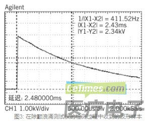
Figure 3: Waveform samples received during detection of the defibrillation surge tester
Energy Measurement Test: Resistance Measurement 1. Before performing the energy measurement test, discharge the resistance with a cold resistance of 100Ω into the defibrillation surge tester.
2. Make sure the defibrillation surge tester is not charged. Follow the manufacturer's prescribed procedures to ensure that this requirement is met. Normally, the instrument should be started and the front panel voltmeter reading should be close to 0 volts.
3. Turn off the defibrillation surge tester.
4. Place the ohmmeter between the energy measurement port and the defibrillation surge tester ground wire. The measured value should be within ± 5% of 100Ω.
5. Perform energy measurement reference test; that is, according to IEC60601-1:2005 standard, no instrument is connected to the output of the defibrillation surge tester. Confirm the output energy and record the result.
6. Repeat steps 2 and 3 above.
7. Place the ohmmeter between the energy measurement port and the defibrillation surge tester ground wire. If the value is slightly lower than the measured value in step 4, wait for the resistor block to cool so that the value is close to the measured value in step 4.
8. Connect the device under test to the defibrillation surge tester and perform an energy measurement test. A difference of less than 10% between the above two results is acceptable.
Energy Measurement Test (IEC 60601-1 Figure 11): Accuracy Evaluation If your Defibrillation Surge Tester is already available for IEC 60601-1:2005 testing, it can be equipped with an energy port for testing as shown in Figure 11. This port can also be used to confirm the exact energy output of the defibrillation surge tester. When using a 5000-V power supply and a 32-μF capacitor, the output energy of any test should be higher than 360J (see Figure 1 herein). The method of operation of this reference test is the same as the first part of the energy measurement test. Since the method of transferring waveform data from the oscilloscope to an Excel spreadsheet differs depending on the oscilloscope used, the following is only a brief operation flow. In addition, users can also obtain a free form from our website. A URL link is provided at the end of the article.
Energy Measurement Test Summary Procedure 1. Remove the load from the defibrillation surge tester output.
2. If necessary, set the defibrillation surge tester to 25-mH, 400-Ω.
3. Measure the resistance of the 100-Ω resistor using the above resistance measurement method.
4. Using an appropriate high-voltage probe (for example, Tektronix P6015), connect the oscilloscope to both ends of the 100-Ω resistor row inside the tester. For most testers, this position is between the energy measurement output and the tester ground.
5. Use a digital oscilloscope that can transfer waveform data to an Excel spreadsheet. Set up the oscilloscope to capture the entire waveform. Set the vertical axis to 1000V/div and the horizontal axis to 2msec/div.
6. Charge the defibrillation surge tester until its internal power supply is charged to 5000V. (In most cases, the power voltage is displayed on the front panel display.) Then, start the defibrillation surge tester.
7. The waveform on the display should show the complete oscilloscope waveform from 0V to 0V. Visit the URL http://Products/Downloads/Energy_calculation_TUV_EC13_10.75ohm_open.xls to see the ideal waveform diagram included in the Excel spreadsheet. If you do not get a complete waveform when using the recommended settings, adjust the settings until the oscilloscope display shows the complete waveform.
8. Transfer the waveform data to an Excel spreadsheet. The method of operation for this step depends on the oscilloscope type used.
9. Open the Excel spreadsheet. Delete waveform data outside the start and end of the waveform. (The noise components of these data can lead to large energy results.)
10. Calculate the result using an Excel spreadsheet. The result should be higher than 360J.
If the result is significantly lower than 360J, check the defibrillation surge tester to correct the cause of the low output energy.
Defibrillation Prevention Test (IEC60601-1 Figures 9 and 10): Accuracy Assessment All of the above methods and discussions related to the power supply of the defibrillation surge tester. A laboratory that follows these guidelines should ensure that the tester is operating properly and that it is suitable for energy measurement tests. However, for the normal mode and differential tests shown in Figures 9 and 10 of IEC60601-1:2005, it must also be ensured that the voltage divider network is operating normally (as shown in the upper part of the red band in Figure 1).
One way to perform this verification is to replace the instrument under test with a known value, that is, instead of all the white parts in Figure 1 herein. This is the most effective verification method; in addition, if you get the expected output value, you can also prove that the entire test setup is correct.
Some manufacturers provide defibrillation pass/fail measurement tools that can be inserted into the above test setup. This pass/fail measurement tool is shipped from the factory with a specific Defibrillation Surge Tester because the same settings cannot be used for all testers in accordance with the IEC 60601-1:2005 tolerance specification. However, uncalibrated pass/fail measurement tools can still be used if necessary to obtain useful information while verifying the test setup and the overall integrity of the defibrillation surge tester.
The defibrillation pass/fail measurement tool is calibrated with a specific tester to accurately calibrate the 1V level on the display device (ie, the oscilloscope). For a detailed description of the entire process and a detailed video demonstration, please visit: http://Library/Defib-5%20Y1-Y2%20Measurement%20setup.pdf and http://YouTubeDefib-5_Setup_and_Operation.html.
Conclusion This paper introduced the new surge test in the IEC 60601-1:2005 standard and introduced some processes and recommendations for simplifying the test and ensuring correct test results. In addition, this article describes some simple ways to ensure that your defibrillation surge tester works properly between calibration cycles. These methods can be used to understand the overall condition of the defibrillation tester and ensure that the tester is connected. We hope these methods will help ensure that all tests are completed when the equipment is working well.